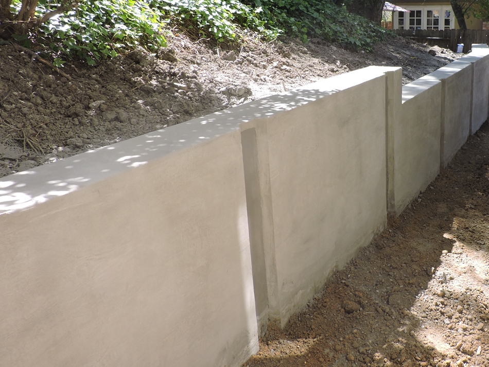
Wall Facing For Concrete Soldier Piles
Design Of Shear Studs Connected To Soldier Pile Walls Concrete Facing Earth Retention Engineering Eng Tips
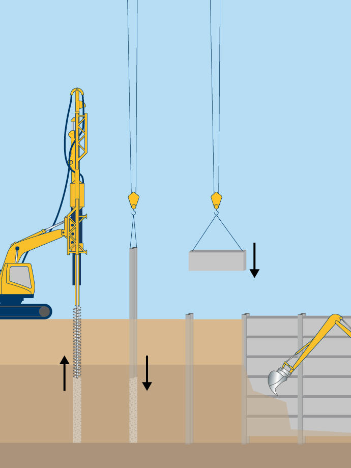
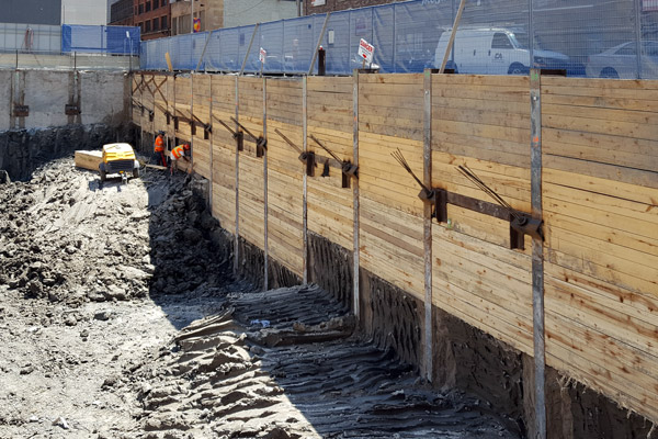
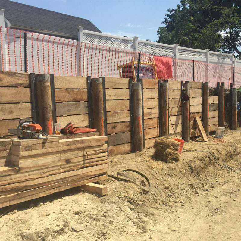
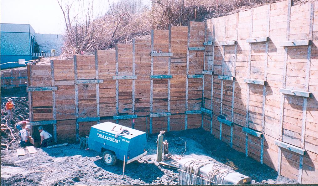
Soldier Piles And Lagging Keller North America

What You Should Know About Soldier Piles Foundation Repair Services Inc

Soldier Pile Wall With Concrete Lagging Youtube
Https Www Malcolmdrilling Com Wp Content Uploads Malcolm Retention Systems Brochure Pdf

Soldier Pile Walls Berliner Wall Deep Excavation Retaining Wall Pile Precast Concrete Panels
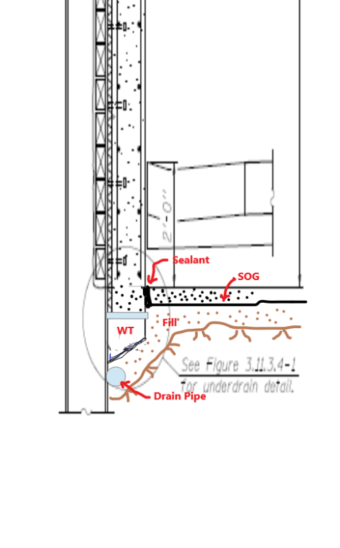
Attach headed studs according to c ms 513 22 and as shown in the plans.
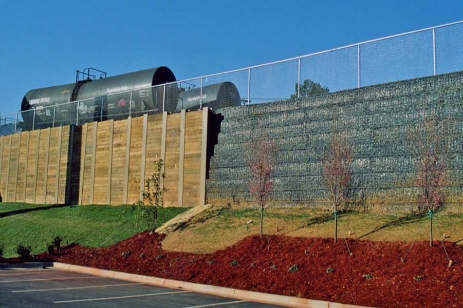
Wall facing for concrete soldier piles.

Specialty Shoring Applications Ebs Geostructural

Vasco Safety Improvements Phase 1 Soldier Pile Wall Work Continues
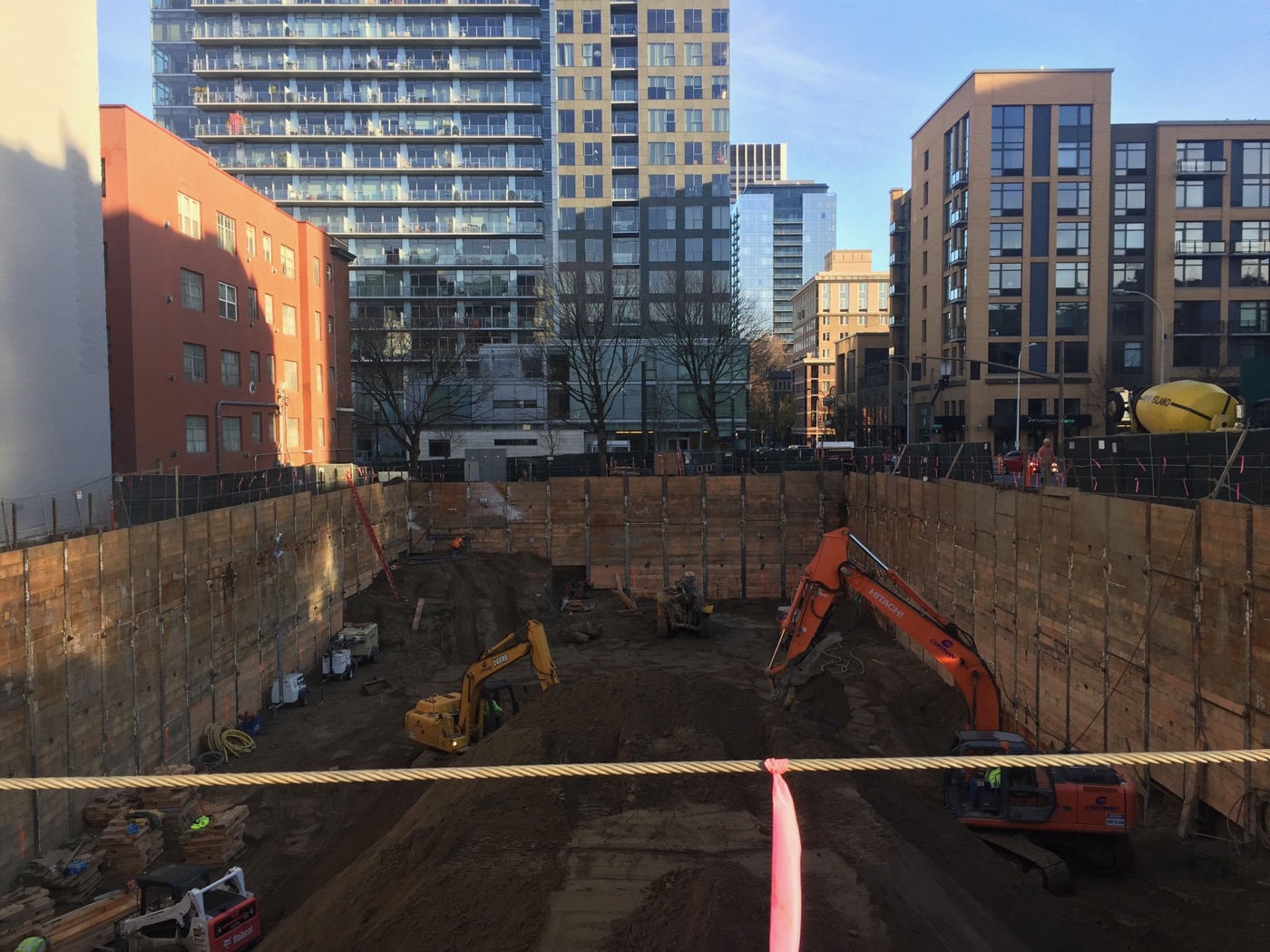
Excavation Support Isherwood Geostructural Engineers
Https Www Dot Ny Gov Divisions Engineering Technical Services Geotechnical Engineering Bureau Geotech Eng Repository Rwiip Ch 2 Retaining Wall Appraisals Pdf

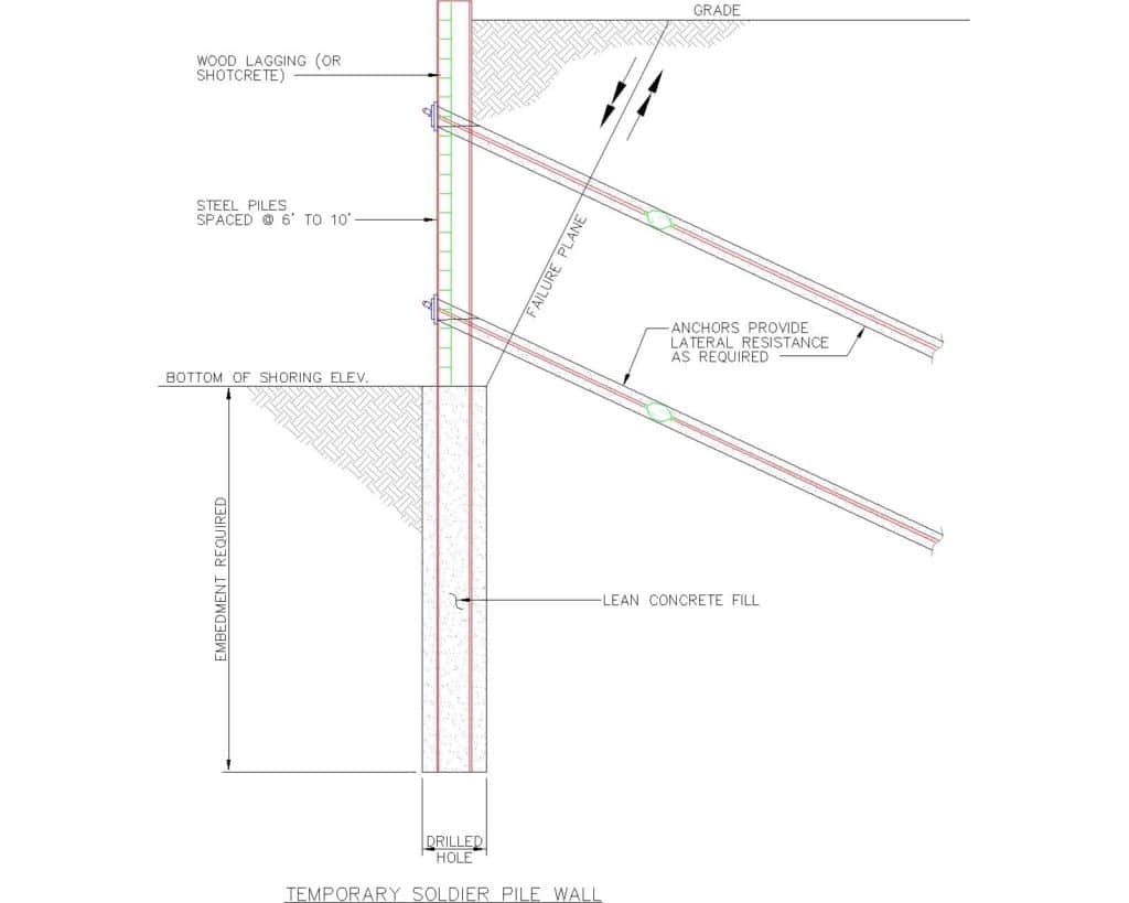
Retaining Walls Cantilever Tieback Drilled Pier Soldier Pile

Can T Solve It Retaining Wall Next To Creek In Very Poor Soils Structural Engineering General Discussion Eng Tips

Image Result For Soldier Piles Retaining Wall Design Retaining Wall Hardscape

Precast Concrete Concrete Retaining Wall Precast Median Barriers Camber Corporation Pittsburgh Pa
Soldier Piles Lagging Phoenix Foundation Company

Soldier Pile Walls Berliner Wall Deep Excavation Retaining Wall Wall Pile
Https Researchrepository Wvu Edu Cgi Viewcontent Cgi Article 4952 Context Etd
Recent Projects

Ut Parks Tower Soldier Pile Retaining Wall And Walkway Dgl Consulting Engineers
Http Www Michigan Gov Documents Mdot I 75 Engineering Report 8 Mile To 12 Mile Appendix D Retaining Wall 604355 7 Pdf
Ground Support Pllc Projects Spinner Building Bellevue Wa

Retaining Structures Geotechnical Capabilities Civil Engineering Engineering Practices Practices Industries Exponent
Services Archive Subsurface Construction Company Llc

Secant Pile Walls Tangent Pile Walls Soldier Piles Deep Excavation
Https Encrypted Tbn0 Gstatic Com Images Q Tbn 3aand9gcssrt8otj1mepkrzfdg9kq61iw6tooik4j9g3gmnwlnurw2fj 9 Usqp Cau
Soldier Pile Walls
Pinnacle Design Build Group Inc Home
Steel Soldier Piles With Cip Wall Connection For Load Transfer To Piles Detail Structuralengineering
Https Www Evergreenrecreation Com Documentcenter View 693 Evergreen Lake North Trail Preliminary Engineering Study 2017 Pdf

Earth Retention Drill Tech Drilling Shoring
Source : pinterest.com
